Introduction
IEC motors can be supplied with a number of different mounting arrangements depending on how the motor is attached to the driven equipment. Where a motor is mounted directly to a gearbox, pump, machine or mounting adaptor, the flange or face dimensions must match the equipment it is being fitted to.
Two of the most common direct mounting arrangements are the B5 flange and the B14 face mounting. A B5 motor normally uses clearance mounting holes around a larger flange, while a B14 motor normally uses threaded mounting holes in a smaller face.
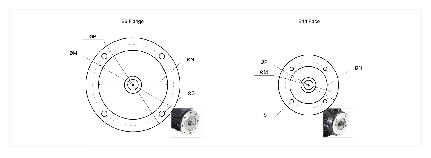
The table and drawing below show the commonly used B5 and B14 dimensions against IEC motor frame size. They can be used to help identify the frame size of an existing motor from its mounting dimensions, or to check the flange or face dimensions required when selecting a replacement motor.
When comparing dimensions, pay particular attention to the locating register diameter and the mounting-hole pitch circle, as these are critical to ensuring that the motor locates and mounts correctly to the driven equipment.
⚠️ The dimensions below apply to standard IEC mounting arrangements. Pumps, gearboxes and other machinery may use special, reduced, enlarged or manufacturer-specific flanges. Always check the actual dimensions and, where available, the manufacturer's dimensional drawing before ordering a replacement motor. ⚠️
IEC B5 Flange and B14 Face Dimensions
Dimensions are in millimetres. Use the locating register and mounting-hole pitch circle when checking whether a motor will fit an existing machine, pump, gearbox or mounting adaptor.
B5 flanges normally use clearance mounting holes, whereas B14 face mountings normally use threaded holes. The locating register diameter is particularly important when checking compatibility with existing equipment.
IEC B5 and B14 flange dimensions by motor frame size
| IEC Frame |
B5 Flange |
B14 Face |
| PCD M |
Register N |
Outside Ø P |
Holes S |
PCD M |
Register N |
Outside Ø P |
Holes S |
| 63 |
115 |
95 |
120 |
7 |
75 |
60 |
90 |
M5 |
| 71 |
130 |
110 |
160 |
10 |
85 |
70 |
105 |
M6 |
| 80 |
165 |
130 |
200 |
12 |
100 |
80 |
120 |
M6 |
| 90S / 90L |
165 |
130 |
200 |
12 |
115 |
95 |
140 |
M8 |
| 100 |
215 |
180 |
250 |
15 |
130 |
110 |
160 |
M8 |
| 112 |
215 |
180 |
250 |
15 |
130 |
110 |
160 |
M8 |
| 132 |
265 |
230 |
300 |
15 |
165 |
130 |
200 |
M10 |
| 160 |
300 |
250 |
350 |
19 |
215 |
180 |
250 |
M12 |
| 180 |
300 |
250 |
350 |
19 |
Not normally provided in this B14 series |
| 200 |
350 |
300 |
400 |
19 |
Not normally provided in this B14 series |
⚠️ These dimensions should be treated as a selection guide only. Always confirm the manufacturer's dimensional drawing before ordering a replacement motor, particularly where the existing equipment uses a non-standard, reduced or enlarged flange.
Useful Links
How to read a motor nameplate to determine key VSD parameters
Star and Delta motor connections
IEC Motor Frame Size vs Shaft Size
All details including photos and images are created by Inverter Drive Supermarket - last revised August 2026