Parker Product Comparison Page - Replacing an AC10 with an AC15
This guide is intended for maintenance engineers, machine builders, OEMs and electricians replacing an existing Parker AC10 with the newer AC15.
Introduction
Although the Parker AC15 replaces the AC10 for most applications up to 30kW, there are several important differences that should be considered before installation. This guide compares the two drives side-by-side, including electrical ratings, dimensions, control terminals, parameter differences and hardware features, making it easier to select and commission the correct replacement.
Throughout this guide we use a traffic light system to highlight the significant differences between the two products:
🟢 No significant difference
🟡 Minor difference - check during installation
🔴 Important difference - must be checked before selection
Quick Summary
| Question |
Answer |
| Suitable Replacement? |
Yes, but there are notable differences |
| Larger than 30kW? |
Use Parker AC20 product range |
| Current Ratings the same? |
Yes, but fewer ratings |
| Same Dimensions? |
Similar but not Identical |
| Same Fixing Centres? |
Yes, for the same Frame Size |
| Same Frame Size Breaks? |
Almost, some ratings are now in a smaller size |
| Same Control Terminals? |
No |
| Same Cable Entry? |
Yes, bottom cable entry |
| Existing parameters transferable? |
No |
| Same Keypad? |
No |
| Same Brake Resistor? |
Check minimum resistance before reuse |
| Same Communication? |
No - AC15 uses Ethernet/Modbus TCP |
| Is the AC15 available in a IP66 version |
No - AC10 IP66 is still a current product range |
 Major Differences
- Parameter names and structure
- Control Terminal references
- Frame Breaks which affect some ratings
- STO now fitted
- Modbus RTU has been replaced with Modbus TCP
- Ethernet is also fitted on Frame Sizes 2 to 5
Image comparison
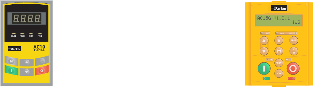
Below are examples of the AC10 and AC15 Frame Size 1. As you can see they are simular but not the same.

kW Rating, Current Ratings and Frame Size.
It is always important when replacing any AC Inverter that the Output Current (Amps) matches the Motor Rated Current. This will vary slightly from range to range manufacturer to manufacturer. If the exact Amp rating does not exist in the AC Inverter range then the next largest unit should be selected. In all AC VSDs the motor current value should be programmed during commissioning to ensure that the motor is thermally protected.
Below you can see that the AC10 and AC15 for the same kW rating have the same Output Current and Input Current. What differs is the kW ratings available and some of the Frame breaks.
230 Vac Single-phase
| AC10 |
AC15 |
| kW Rating |
Output Amps |
Input Amps |
Frame Reference |
kW Rating 🟡 |
Output Amps 🟢 |
Input Amps 🟢 |
Frame Reference 🟡 |
| 0.18 kW |
1.5 A |
4 A |
1 |
- |
- |
|
- |
| 0.37 kW |
2.5 A |
5.8 A |
1 |
0.37 kW |
2.5 A |
5.8 A |
1 |
| 0.55 kW |
3.5 A |
7.6 A |
1 |
- |
- |
|
- |
| 0.75 kW |
4.5 A |
10 A |
1 |
0.75 kW |
4.5 A |
10 A |
1 |
| 1.1 kW |
5 A |
10.8 A |
2 |
- |
- |
|
- |
| 1.5 kW |
7 A |
14 A |
2 |
1.5 kW |
7 A |
14 A |
1 🔴 |
| 2.2 kW |
10 A |
20 A |
2 |
2.2 kW |
10 A |
20 A |
2 |
400 Vac Three-phase
| AC10 |
AC15 |
| kW Rating |
Output Amps |
Input Amps |
Frame Reference |
kW Rating 🟡 |
Output Amps 🟢 |
Input Amps 🟢 |
Frame Reference 🟡 |
| 0.18 kW |
0.6 A |
1.1 A |
1 |
- |
- |
|
- |
| 0.37 kW |
1 A |
1.5 A |
1 |
0.37 kW |
1.2 A |
1.5 A |
1 |
| 0.55 kW |
1.5 A |
2.1 A |
1 |
- |
- |
|
- |
| 0.75 kW |
2 A |
3 A |
2 |
0.75 kW |
2 A |
3 A |
2 |
| 1.1 kW |
3 A |
4 A |
2 |
- |
- |
|
- |
| 1.5 kW |
4 A |
5 A |
2 |
1.5 kW |
4 A |
5 A |
2 |
| 2.2 kW |
6.5 A |
7.5 A |
2 |
2.2 kW |
6.5 A |
7.5 A |
2 |
| 3.7 kW |
8 A |
10.5 A |
3 |
- |
- |
|
- |
| 4 kW |
9 A |
11 A |
3 |
4 kW |
9 A |
11 A |
2🔴 |
| 5.5 kW |
12 A |
14 A |
3 |
5.5 kW |
12 A |
14 A |
3 |
| 7.5 kW |
17 A |
18.5 |
4 |
7.5 kW |
17 A |
18.5 A |
3 🔴 |
| 11 kW |
23 A |
24 A |
4 |
11 kW |
23 A |
24 A |
4 |
| 15 kW |
32 A |
36.5 A |
5 |
15 kW |
32 A |
36.5 A |
4 🔴 |
| 18.5 kW |
38 A |
44 A |
5 |
18.5 kW |
38 A |
44 A |
5 |
| 22 kW |
44 A |
51 A |
5 |
22 kW |
44 A |
51 A |
5 |
| 30 kW |
60 A |
70 A |
6 |
30 kW |
60 A |
70 A |
5 🔴 |
| above 30kW |
|
|
|
AC20 Product Range |
|
|
|
Frame Size Comparison
A Frame Reference is given to distinguish the individual sizes within a product range. In this instance the Frame reference is the same but the dimensions differ between the ranges. Frame Size 1 AC10 is not the same size as a Frame Size 1 AC15 however where possible the fixing dimensions have been kept the same.
The table below gives the overall dimension and fixing comparison. Where there is no AC15 equivalent rating the next rating has been given for completeness. The Height shown in parentheses is the total including mounts and brackets.
230Vac Single-Phase
| AC10 |
AC15 |
| Frame Reference |
kW Ratings |
H x W x D (Overall) |
h x d (Fixing) |
Fixings |
Frame Reference 🟡 |
kW Ratings |
H x W x D (Overall) 🟡 |
h x d (Fixing) 🟢 |
Fixings 🟢 |
| 1 |
0.18 kW |
138 (153) x 80 x 135 |
127 x 70 |
4 x M4 |
1 |
0.37 kW |
138 (176) x 82 x 145 |
128 x 70 |
4 x M4 |
| 0.37 kW |
0.37 kW |
| 0.55 kW |
0.75 kW |
| 0.75 kW |
0.75 kW |
| 2 |
1.1 kW |
180 (195) x 106 x 150 |
170 x 94 |
4 x M4 |
1.5 kW 🔴 |
| 1.5 kW |
1.5 kW 🔴 |
| 2.2 kW |
2 |
2.2 kW |
180 (185) x 109 x 180 |
170 x 94 |
4 x M4 |
400Vac Three-phase
| AC10 |
AC15 |
| Frame Reference |
kW Ratings |
H x W x D (Overall) |
h x d (Fixing) |
Fixings |
Frame Reference 🟡 |
kW Ratings |
H x W x D (Overall) 🟡 |
h x d (Fixing) 🟢 |
Fixings 🟢 |
|
1
|
0.18 kW |
138 (153) x 80 x 135
|
128 x 70
|
4 x M4
|
1 |
0.37kW |
138 (176) x 82 x 145 |
128 x 70 |
4 x M4 |
| 0.37 kW |
0.37kW |
| 0.55 kW |
2
|
0.75 kW 🔴 |
180 (185) x 109 x 180
|
170 x 94
|
4 x M4
|
|
2
|
0.75 kW |
180 (195) x 106 x 150
|
170 x 94
|
4 x M4
|
0.75 kW |
| 1.1 kW |
1.5 kW |
| 1.5 kW |
1.5 kW |
| 2.2 kW |
2.2 kW |
|
3
|
3.7 kW |
235 (250) x 138 x 152
|
225 x 126
|
4 x M5
|
4 kW 🔴 |
| 4 kW |
4 kW 🔴 |
| 5.5 kW |
3 |
5.5 kW |
238 (282) x 142 x 185 |
225 x 126 |
4 x M5 |
| 4 |
7.5 kW |
265 (280) x 156 x 170 |
255 x 146 |
4 x M5 |
7.5 kW 🔴 |
| 11 kW |
4 |
11 kW |
260 (322) x 161 x 196 |
255 x 146 |
4 x M5 |
|
5
|
15 kW |
340 (355) x 205 x 196
|
330 x 194
|
4 x M5
|
15 kW 🔴 |
| 18.5 kW |
5
|
18.5 kW |
340 (402) x 210 x 221
|
330 x 194
|
4 x M5
|
| 22 kW |
22 kW |
| 6 |
30 kW |
435 x 265 x 235 |
412 x 235 |
4 x M6 |
30 kW 🔴 |
Although the fixing centres have generally been retained, several power ratings now occupy different frame sizes. Always check the overall dimensions before ordering replacement units.
Keypad Differences
In both instances the Keypad is fixed up to 22kW with an alternative Keypad available for door mounting.
Front Mounted Keypad Summary:
🟢Parameter Navigation and Local Control Keys are the same
🟡 Display and Indicators are similar - LED 7 Segment and separate indicators vs LCD 7 Segment with LCD Indicators
🔴 Parameter Structure is different

Door Mounted Keypad
The Door mounted Keypad is different for the AC10 and AC15 and is not interchangeable. The AC15 uses the 6901 Keypad which is a multiline alpha-numeric Keypad. We would recommend using the 6901 for ease of use when programming the AC15 using the keypad.
Key Hardware Differences
Internal Braking Unit (DBr)
The Internal Braking switch varies from rating to rating. Check to ensure that any resistor fitted is suitable for the replacement unit. The most critical value in the braking circuit is the minimum resistance value. Using a resistor that is smaller than the minimum value will cause damage.
230Vac Single-phase units
| |
kW Rating |
0.18 kW |
0.37 kW |
0.55 kW |
0.75 kW |
1.1 kW |
1.5 kW |
2.2 kW |
| AC10 |
Minimum Braking Resistor (Ohms) |
60 |
60 |
60 |
60 |
60 |
60 |
60 |
| AC15 |
- |
80 🔴 |
- |
80 🔴 |
- |
80 🔴 |
80 🔴 |
400 Vac Three-phase units
| |
kW Rating |
0.18kW |
0.37kW |
0.55kW |
0.75kW |
1.1kW |
1.5kW |
2.2kW |
3.7kW |
4kW |
5.5kW |
7.5kW |
11kW |
15kW |
18.5kW |
22kW |
30kW |
| AC10 |
Min Braking Resistor (Ohms) |
120 |
120 |
120 |
120 |
120 |
120 |
120 |
100 |
100 |
100 |
100 |
50 |
35 |
35 |
35 |
25 |
| AC15 |
- |
145 🔴 |
- |
145 🔴 |
- |
95 |
90 |
- |
90 |
90 |
90 |
50 |
30 |
30 |
30 |
25 |
Control Terminals Differences
Like the AC10 the AC15 cannot be expanded so the I/O cannot be increased.


| |
Frame Size |
Analogue Input 🟢 |
Analogue Output 🟢 |
Digital Input 🟢 |
Digital Output 🟡 |
Relay 🟡 |
Communication 🔴 |
| AC10 |
1, 2, 3, 4, 5 |
2 |
2 |
6 |
1 |
1 (Change Over) |
Modbus RTU (Twin-wire) |
| 6 |
2 |
2 |
8 |
2 |
1 (Change Over) |
Modbus RTU (Twin-wire) |
| AC15 |
1** |
2 |
2 |
6 |
0* |
1 (Normally Open) |
Modbus TCP (RJ45) |
| 2, 3, 4 and 5 |
2 |
3 |
8 |
0* |
1 (Normally Open) |
Modbus TCP or Ethernet (RJ45) |
*2 Digital Inputs are available to be programmed as Digital Outputs if required.
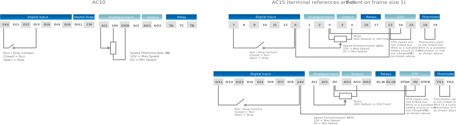
** Terminal references differ for Frame Size 1, Full comparison given below.
Additional Useful Notes:
- AC15 has a dedicated PTC Input. This must be linked out if PTCs are not connected
- AC15 is fitted with Dual Input STO. This must be linked out if a Safety Circuit is not fitted
- AC15 does not have a dedicated 10V source for an external potentiometer, however Analogue Output 2's default setting is 'Fixed 10V' so this can be used as a 10V source.
- AC15 control terminal references differ on Frame Size 1, the default wiring diagram below gives both variations
Default Wiring:
Default wiring is an example of how each unit can be wired up for basic stop and start control with a potentiometer. For the AC15 STO and Thermistor links have been included for completeness.
Essential Parameters to Check After Replacement
The parameter structure is different between the AC10 and AC15. For more details see our Easy Start Guides. These documents give you instructions on how to navigate and change the parameters.
Below are the parameter references for the most common and essential parameters.
| |
AC10 |
AC15 |
| Parameter Function |
Parameter Reference |
Default |
Units |
Parameter Reference |
Default |
Units |
| Motor Current |
F803 |
VSD Rated Current |
A |
P0222 |
VSD Rated Current |
A |
| Motor Voltage |
F802 |
Rating Dependant |
V |
P0223 |
Rating Dependant |
V |
| Motor Power |
F801 |
VSD kW Rating |
kW |
P0227 |
VSD kW Rating |
kW |
| Base Motor Speed |
F805 |
1450 |
rpm |
P0226 |
1450 |
rpm |
| Acceleration Time 🟡 |
F114 |
5 |
s |
P0466 |
10 |
s |
| Deceleration Time 🟡 |
F115 |
5 |
s |
P0467 |
10 |
s |
| Maximum Frequency 🟡 |
F111 |
50 |
Hz |
P0457 |
1500 |
rpm |
| Minimum Frequency 🟡 |
F112 |
0.5 |
Hz |
P1797 |
0 |
% |
Additional Useful Information:
- On the AC15 Parameter P0002 is an essential parameter that determines what parameters can be seen. Setting this value to 2, ensures you are able to see all parameters. We recommend setting this value to 2 during commissioning.
- As default the AC10 powers up in local control (Keypad), the AC15 as default powers up in remote control (Terminals)
- If you need Keypad control on the AC15 switching to local control is easily done by pressing and holding the Stop Key on the Keypad.
- Both units can be programmed using DSE-Lite however the parameters cannot be taken from the AC10 and put in to the AC15 using this software.
Common Mistakes when using the AC15
- Links not fitted - Thermistor and STO inputs need to be linked if they are not being used. AC15 will trip if these links are not fitted
- Limited Parameter View - Set P0002 to 2 to see all parameters
- Unable to locate 10V for external potentiometer - AO2 can be used as 10V source for pot, default value is 10V fixed
Conclusion
The Parker AC15 is the recommended replacement for the AC10 up to 30kW. Although the electrical performance remains largely unchanged, installers should pay particular attention to the revised parameter structure, control terminals, frame sizes and safety inputs during commissioning.
Useful Additional Information
Buy a Parker AC15 (please log in before following the link)
Easy Start Guides
Help and Guidance Documents
All images and content have been created by Inverterdrive Supermarket Ltd. Last Revised Aug 2026