ABB ACS180 Easy Start Guide
This ABB ACS180 Easy Start Guide explains how to wire, configure, commission, and operate ABB ACS180 variable speed drives, including parameter setup, keypad operation, STO wiring, braking resistors, potentiometer speed control, and sensorless vector configuration.
This online guide is designed for easy reading on mobile devices; a PDF version is also available to download.
Contents
Section 1 - Power and Motor Connections (Single Phase)
Section 2 - Power and Motor Connections (Three Phase)
Section 3 - Motor Connections - Star and Delta
Section 4 - Parameter Overview
Section 5 - Parameters to Review Before Use
Section 6 - How to Operate from the Keypad
Section 7 - How to Enable Sensorless Vector Mode
Section 8 - How to Connect and Configure a Potentiometer for Remote Speed Control
Section 9 - How to Connect and Configure a Run Forward or Run Reverse Switch
Section 10 - How to Connect and Configure a Run/Stop Switch with Forward/Reverse Selection
Section 11 - How to Configure 3-Wire Control with Run and Stop Pushbuttons and a Forward/Reverse Selection Switch
Section 12 - Brake Resistor Connection
Section 13 - STO (Safe Torque Off) Connections
Section 14 - How to Reset the Inverter to Factory Defaults
Power and Motor Connections (Single Phase)
Notes
- This illustration is based on the 0.37kW rating (size R0). The terminals for other ratings are similarly labelled.
- The supply voltage must match the inverter specification.
- Applying 400V to a 230V unit will cause damage to the AC inverter.
- The order of the three motor phases determines the initial direction in which the motor turns; this can be reversed by swapping two of the phases.
- You must use screened or armoured cable between the inverter and motor and ensure it is grounded as shown.
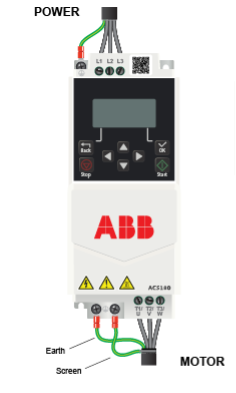
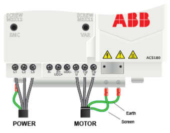
Power and Motor Connections (Three Phase)
Notes
- These illustrations are based on the 0.75kW 400V rating (size R0) and the 15kW 400V rating (size R4). The terminals for other ratings are similarly labelled.
- The supply voltage must match the inverter specification.
- The order of the three motor phases determines the initial direction in which the motor turns; this can be reversed by swapping two of the phases.
- You must use screened or armoured cable between the inverter and motor and ensure it is grounded as shown.
Motor Connections - Star and Delta
Introduction
- Dual-voltage induction motors typically include terminal boxes with six points. The points can be connected together with links in one of two ways to suit one of the two rated voltages.
- The two ways of connecting the links are shown below. These are known as 'Star' (the higher voltage) and 'Delta' (the lower voltage).
- The selection of Star or Delta is not optional and must match the supply voltage; incorrect selection will result in poor torque performance.
- Dual-voltage motor nameplates include symbols to represent voltage and full-load current in each configuration.
- Delta is represented by a triangle, and Star is represented by a Y (Wye).
Motor Connected in Star (or Wye)
For safety purposes, Star (shown above) is the default configuration for small motors, usually up to 3kW.
Only two links are required for Star. There will be three links, with two doubled up in case the motor needs to be set up for Delta operation.
The order of the three phase connections determines the direction in which the motor turns; to change the motor direction, swap two motor phase connections.
When wired in Star, the correct motor current value needs to be read from the motor nameplate; this will be the lower of the two current values given.
Motor Connected in Delta
Delta (shown above) is the default configuration for most 2-pole and 4-pole motors above 4kW.
Three links are required for Delta. When changing to Star, do not discard the third link; double it up for future use.
The order of the three phase connections determines the direction in which the motor turns; to change the motor direction, swap two motor phase connections.
When wired in Delta, the correct motor current value needs to be read from the motor nameplate; this will be the higher of the two current values given.
Important Information
The manufacturer recommends that the motor cable includes a safety earth and a screen. The earth conductor and screen must be earthed at both the motor and the ACS180. This ensures that the motor is correctly earthed for safety and that the noisy motor cables (high-frequency noise) are correctly terminated to reduce the risk of electromagnetic interference with surrounding equipment.
Parameters
Overview
The ACS180 contains a number of settings that can be changed to tailor it for use in a wide range of applications. These settings are known as parameters. In the ACS180, the parameters are grouped together in different lists and then by number. For example, parameter 99.06 (Motor Current) is parameter group 99, parameter number 06.
The parameters contain critical information required for correct operation of the ACS180. All AC inverters are supplied with a set of default parameter values. These will differ from product to product and from manufacturer to manufacturer, so it is important to review the most critical parameters. Below is a recommendation of the parameters within the ACS180 that should be reviewed during commissioning and changed to suit the motor and application. The parameters listed are intended to provide a starting point for basic operation of the ACS180 AC inverter, and it is likely that other parameters will need to be changed to achieve the required operation. The ACS180 firmware manual should be used for all other parameters.
Parameters to Review Before Use
We suggest that the following parameters are reviewed before operation. The suggestions below are based on simple V/F control (scalar) of a 50Hz induction motor. Control parameters - stop, start, direction, and speed reference - are not included in the table below and can be found in the Speed Control and Control Wiring sections.
Table 1 - Main Parameters
| Parameter |
Parameter Description (Units) |
Default Value (Units) |
Required Setting - Useful Information |
| 21.03 |
Stop Mode |
1 - Ramp to Stop |
The default will suit most applications. Set to 0 for Coast to Stop (uncontrolled). |
| 28.72 |
Acceleration Time (sec) |
3 (secs) |
The default will suit most applications. For fan loads, a longer time may be required, for example 10 secs. |
| 28.73 |
Deceleration Time (sec) |
3 (secs) |
The default will suit most applications. For fan loads, a longer time may be required, for example 10 secs. |
| 30.13 |
Minimum Frequency |
-50 (Hz) |
This parameter is only valid if 99.04 is set to 1. This sets the minimum speed in Hz. A value of at least 20Hz would be sensible for most fan loads. |
| 30.14 |
Maximum Frequency |
50 (Hz) |
This parameter is only valid if 99.04 is set to 1. This clamps the maximum speed to 50Hz, which suits most applications. |
| 97.01 |
Switching Frequency (kHz) |
4 (kHz) |
The default will suit most applications. Increase it to reduce motor noise, but with caution, as this will de-rate the unit. |
| 97.20 |
V/F Ratio |
0 - Linear |
The default will suit many applications. Set to 1 - Squared for centrifugal loads such as fans and pumps. |
| 99.03 |
Motor Type |
0 - Induction Motor |
This must be set to match the motor type. Most industrial motors are AC induction motors. |
| 99.04 |
Motor Control Mode |
1 - V/F Scalar |
The default will suit many applications. If more starting torque is required, we suggest setting this to 0 and following the instructions given in the Sensorless Vector Setup section below. |
| 99.06 |
Motor Current (A) |
Rating dependent |
Set to the value given on the motor nameplate. Ensure this value matches the wiring of the motor (see motor connection details above). |
| 99.07 |
Motor Voltage (V) |
Rating dependent |
Set to the value given on the motor nameplate; in most instances, this will match your supply voltage. |
| 99.09 |
Motor Speed (rpm) |
Rating dependent |
Set to the value given on the motor nameplate. Sometimes this is shown as min-1 rather than rpm. |
| 99.11 |
Motor Power Factor |
0 |
Set to the value on the nameplate. Power factor is often referred to as Cosφ on the motor nameplate. |
How to Set a Parameter Value
This is the home screen. To return to this screen, press the "Back" button repeatedly.
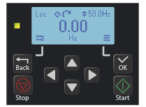
Press OK to open the Main Menu.
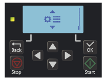
Use the Up and Down arrow keys to scroll through the five submenus, which are on a loop.

 Select the Parameter submenu and press OK.
This will display three options. The full parameter list is highlighted, as indicated below
In this example, we will change parameter 99.06, Motor Current, which is in the full parameter list.
With the parameter list highlighted, press OK to select it.
If the parameter list is not highlighted, use the arrow keys to select it.
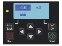
Once the parameter list is selected, all parameter groups will appear in a list format.
Use the Up and Down arrow keys to move to parameter group 99. Press OK to select it.
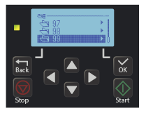
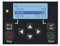
The parameter group is now shown in the top left corner of the screen, and the full parameter reference is displayed.
Use the Up and Down arrow keys to highlight parameter 99.06 (Motor Current). The value can be viewed without selecting the parameter. In this example, it is 1.55A.
Press OK to select the parameter so it can be edited.
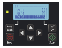
The full parameter reference is now shown in the top left-hand corner of the screen.
The parameter value is shown with its units. Use the Left and Right arrows to select the digit you want to change, and the Up and Down arrows to change the value.
In this example, we have changed parameter 99.06 to 1.42A. Press OK to save the changes.
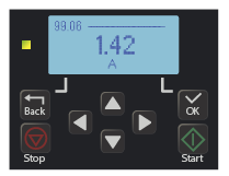
The parameter value is now saved and is visible in the parameter list.
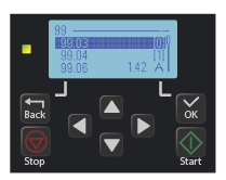
Press "Back" to return to the parameter group, where another parameter can be selected, or press "Back" repeatedly to return to the home screen.
How to Operate from the Keypad
Press the "Back" button repeatedly until the "Loc Rem" option is visible, as shown below.
Press "OK" to toggle between "Loc" (Local) and "Rem" (Remote). Ensure "Loc" is highlighted as indicated. There is no need to confirm the selection.
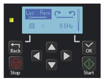
Press the "Back" button repeatedly until the home screen (speed display) is visible. The display will show "Loc" in the top left when in Local control and "Rem" when in Remote control.
Use the arrow keys to set the local speed reference as required. A negative value will change direction. In this example, the speed reference has been set to 40Hz. The speed reference can be seen in the top right, as shown below.
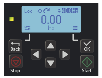
Press the green Start button, and the motor will accelerate to the speed reference. The output speed is indicated in the centre of the display.
The arrow icons rotate to indicate that the motor is running. While the motor is running, the speed can be changed using the Up and Down arrow buttons. The arrow buttons will become dotted while the motor is accelerating or decelerating.
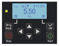
Press the "Stop" button to stop the motor. While the motor is decelerating, the output speed in the centre of the display will reduce to zero.
The arrow icons will rotate until the motor has stopped.
Note: The local speed reference value is stored and will be retained after a power cycle.
How to Enable Sensorless Vector Mode
The standard operating mode for the ACS180 range is V/F. This is the simplest form of operation and controls the volts and frequency to vary the speed of a standard induction motor.
The ACS180 range can also be operated in Sensorless Vector Mode. This can improve motor performance without requiring a separate feedback device such as an encoder.
To improve performance, Sensorless Vector Control requires a number of values to build a "model" of the motor it is controlling. These are given in the table below.
Note: Sensorless Vector Control is not suitable where the motor rating is significantly lower than the AC inverter rating, or where more than one motor is being controlled from a single inverter.
Follow these steps when setting up the ACS180 for Sensorless Vector Control.
- Reset to factory default values ⇒ Resetting to factory defaults is only required during initial setup, as this will reset all parameters.
- Set the motor values as given in Table 1 ⇒
- Ensure the motor is in Local control ⇒
Table 2 - Sensorless Vector Parameters
| Parameter |
Parameter Description (Units) |
Default Setting (Units) |
Required Setting - Useful Information |
| 23.12 |
Acceleration Time (sec) |
3 (secs) |
This parameter is only valid when Motor Control Mode (99.04) is set to Sensorless Vector. |
| 23.13 |
Deceleration Time (sec) |
3 (secs) |
This parameter is only valid when Motor Control Mode (99.04) is set to Sensorless Vector. |
| 99.04 |
Motor Control Mode |
1 - Scalar (V/F) |
Set to 0 for Sensorless Vector Control. |
| 99.13 |
ID Run Request |
3 - Standstill |
The default setting is required in this instance. The parameter resets to 0 once auto-tune (ID Run) is complete. |
Set parameter 99.04 to 0 for Vector Control. When selected, an AFF6 warning will appear; this can be ignored.
Press "Back" repeatedly until you can see the home screen. The speed will now be shown in rpm rather than Hz.
Press "Start" on the keypad. The ACS180 will now start the auto-tune (ID Run). The arrows will move clockwise, but the motor will not turn during the standstill auto-tune.
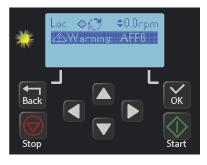
The green indicator will flash until the auto-tune is complete.
Note: You must ensure the motor is unloaded, but not bare shaft, when operated in Vector Control; otherwise, it may trip on overspeed (7310).
How to Connect and Configure a Potentiometer for Remote Speed Control
If speed control via the integrated keypad is unsuitable for the application, a remote potentiometer can be used instead. This allows motor speed to be controlled from a more convenient location, such as a cabinet door or the machine itself. A potentiometer rated between 1kΩ and 10kΩ can be used.
Table 3 - Remote Potentiometer Parameter Settings
| Parameter |
Parameter Description (Units) |
Default Setting (Units) |
Required Setting - Useful Information |
| 28.11 |
Frequency Reference EXT1 |
1 - Analogue Input 1 |
Set to 2 - Analogue Input 2. |
| 12.25 |
AI2 Unit Selection |
10 - mA |
Set to 2 - Volts. |
| 30.13 |
Minimum Frequency (Hz) |
-50Hz |
The default will suit many applications. If a minimum running speed is required, set it to 20Hz, for example. |
| 30.14 |
Maximum Frequency (Hz) |
50Hz |
The default will suit many applications. Change it if required. |
Parameters must be set and the potentiometer wired before operation.
Overview:
- To use a potentiometer with the ACS180, the drive must be set to "Remote" control. Press "Back" repeatedly until the display shows "Loc Rem". Use the "OK" button to select between "Loc" and "Rem". Press "Back" to return to the home screen; "Rem" should be shown in the top left of the home screen.
- A wiring diagram is shown opposite. The most important connection is the centre terminal, or wiper. The wiper will output a variable voltage between 0V and 10V and should be connected to AI2 (terminal 15) on the ACS180. It is this voltage that provides the speed signal, with 0V being the slowest and 10V being the fastest.
- It is good practice to ensure that, when fully clockwise, the potentiometer output is at its maximum, in this case 10V. If the rotation of the potentiometer is the opposite (0V), reverse the connections to AGND (16) and 10V (23).
Operation:
- When the ACS180 receives a run signal, the VSD will run at the speed determined by the position of the potentiometer.
- When AI2 receives 0V, it will run at minimum speed, which is 0Hz by default.
- When AI2 receives 10V, the VSD will run at maximum speed, which is 50Hz by default.
- The minimum speed can be altered if required by changing parameter 30.13.
- The maximum speed can be altered if required by changing parameter 30.14.
How to Connect and Configure a Run Forward and Run Reverse Switch
If keypad control is unsuitable, a remote switch can be used instead. Our example shows a three-position switch, but a two-position switch can be used if direction control is not required.
| Parameter |
Parameter Description (Units) |
Default Setting (Units) |
Required Setting - Useful Information |
| 20.01 |
External Commands EXT1 |
2 - Run/Stop with Reverse Select |
Set to 3 - Run Forward and Run Reverse. |
| 30.13 |
Minimum Frequency (Hz) |
-50Hz |
Set to the required speed reference value, for example 20Hz. |
Parameters must be set and the switch wired as shown before operation.
Overview:
- To use the terminals on the ACS180, the AC inverter must be set to "Remote" control mode. To switch to Remote control, press "Back" repeatedly until the display shows "Loc Rem". Pressing "OK" toggles between Local and Remote control. Press "OK" when Remote is selected.
- The wiring diagram for a three-position switch is given above. Terminal 21 (+24V) is the positive logic (PNP) for digital inputs 8 (DI1) and 9 (DI2).
- The switch should have two normally open contacts, one connected between terminals 21 (24V) and 8 (DI1), and the other between terminals 21 (24V) and 9 (DI2). The centre position should be open circuit.
- It is important that the link cable is fitted; otherwise, the switch will not function.
Operation:
- When a connection is made between terminals 21 (24V) and 8 (DI1), the motor will run forward.
- When a connection is made between terminals 21 (24V) and 9 (DI2), the motor will run in reverse.
- With both contacts open (centre position), the motor will stop.
- The motor speed is determined by parameter 30.13. A speed reference is required; with a zero speed reference, the motor will run at zero speed and remain stationary.
How to Connect and Configure a Run/Stop Switch with Reverse Selection
If keypad control is unsuitable, a remote switch can be used instead. Our example shows two two-position switches; however, one switch can be used if direction control is not required.
| Parameter |
Parameter Description (Units) |
Default Setting (Units) |
Required Setting - Useful Information |
| 20.01 |
External Commands EXT1 |
2 - Run/Stop with Reverse Select |
Set to 2 - The default value is required. |
| 30.13 |
Minimum Frequency (Hz) |
-50Hz |
Set to the required speed reference value, for example 20Hz. |
Parameters must be set and the switch wired as shown before operation.
Overview:
- To use the terminals on the ACS180, the AC inverter must be set to "Remote" control mode. To switch to Remote control, press "Back" repeatedly until the display shows "Loc Rem". Pressing "OK" toggles between Local and Remote control. Press "OK" when Remote is selected.
- The wiring diagram for two two-position switches is given above. Terminal 21 (+24V) is the positive logic (PNP) for digital inputs 8 (DI1) and 9 (DI2).
- The switches should have normally open contacts, one connected between terminals 21 (24V) and 8 (DI1), and the other between terminals 21 (24V) and 9 (DI2).
- It is important that the link cable is fitted; otherwise, the switch will not function.
Operation:
- When a connection is made between terminals 21 (24V) and 8 (DI1), the motor will run in the direction determined by DI2.
- When a connection is made between terminals 21 (24V) and 9 (DI2), this will select the reverse direction. It does not stop or start the ACS180. With no switch connected (open circuit), forward direction is selected.
- When the connection is open between terminals 21 (24V) and 8 (DI1), the motor will stop.
- The motor speed is determined by parameter 30.13. A speed reference is required; with a zero speed reference, the motor will run at zero speed and remain stationary.
How to Connect and Configure 3-Wire Control with Run and Stop Pushbuttons and a Forward and Reverse Selector Switch
If keypad control is unsuitable, a remote switch can be used instead. Our example shows two momentary switches and a two-position switch. The two-position switch can be omitted if direction control is not required.
| Parameter |
Parameter Description (Units) |
Default Setting (Units) |
Required Setting - Useful Information |
| 20.01 |
External Commands EXT1 |
2 - Run/Stop with Reverse Select |
Set to 5 - 3-wire control. |
| 20.05 |
Ext1 In3 Source |
0 - Always Off |
Set to 4 - DI3 input for direction selection. |
| 22.22 |
Constant Speed Sel1 |
4 - DI3 Function (Speed) |
Set to 5 - DI3 can be reassigned. |
| 28.22 |
Constant Frequency Sel1 |
4 - DI3 Function (Frequency) |
Set to 5 - DI3 can be reassigned. |
| 30.13 |
Minimum Frequency (Hz) |
-50Hz |
Set to a positive value, for example 10Hz. |
Parameters must be set and the switches wired as shown before operation.
Overview:
- To use the terminals on the ACS180, the AC inverter must be set to "Remote" control mode. To switch to Remote control, press "Back" repeatedly until the display shows "Loc-Rem". Pressing "OK" toggles between Local and Remote control. Press "OK" when Remote is selected.
- The wiring diagram for two momentary switches and a two-position switch is given above. Terminal 21 (+24V) is the positive logic (PNP) for digital inputs 8 (DI1), 9 (DI2), and 10 (DI3).
- The green Run switch should have normally open contacts connected between terminals 21 (24V) and 8 (DI1), and the red Stop switch should have a normally closed contact connected between terminals 21 (24V) and 9 (DI2).
- The two-position direction selection switch should be connected between terminals 21 (24V) and 10 (DI3). This can be omitted if reverse direction is not required.
- It is important that the link cable is fitted; otherwise, the switches will not function.
Operation:
- When a connection is made between terminals 21 (24V) and 8 (DI1), the motor will run.
- When a connection is broken between terminals 21 (24V) and 9 (DI2), the motor will stop.
- When a connection is made between terminals 21 (24V) and 10 (DI3), reverse direction is selected.
- The motor speed is determined by parameter 30.13. A speed reference is required; with a zero speed reference, the motor will run at zero speed and remain stationary.
Brake Resistor Connection
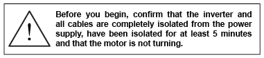
By default, the ACS180 automatically extends the deceleration time if it cannot slow a high-inertia load in the specified time.
For applications that require faster stopping, dynamic braking can be used to maintain or reduce the deceleration time by safely absorbing the excess energy generated during braking.
This requires the addition of a braking resistor, which dissipates the regenerated energy as heat. The resistor must be correctly sized to suit both the VSD and the application.
In addition, the ACS180 must be configured to disable voltage monitoring to enable the braking resistor. If voltage monitoring is disabled without a resistor connected, the VSD may trip with fault code 3210.
| Parameter |
Parameter Description (Units) |
Default Setting (Units) |
Required Setting - Useful Information |
| 30.30 |
Overvoltage Control |
1 - Enabled |
Set to 0 - Disabled. Do not disable this unless the ACS180 is fitted with a suitable braking resistor. |
Connect the brake resistor to the R+UDC and R- terminals on the ACS180 as shown. The order of the connections is unimportant. Dynamic braking is not available on R0 and R1 frame sizes, and these terminals will not be present.
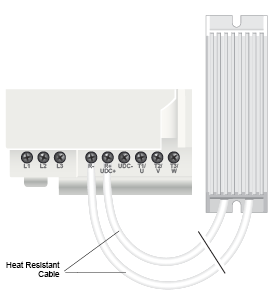
The brake resistor may get hot in operation, so ensure it is mounted in a suitable position away from the ACS180 and other items.
It is essential that a resistor of the correct rating is used. Details can be found in our product listings or the ACS180 hardware manual.
STO (Safe Torque Off) Connections
 This section is an overview only. You must always refer to the manual provided by the manufacturer for full details of STO functionality.
Important Information:
- Safe Torque Off (STO) is a feature that is included on all ACS180 products.
- STO provides a facility to disable the output of the VSD so that the motor it is controlling cannot be operated, i.e. no torque can be applied. However, it does not provide any form of braking, so it will not prevent the load from rotating the motor.
- The STO function is only effective when wired to suitable safety devices that detect an unsafe situation. A safety assessment of the machinery is required by suitably qualified personnel to identify what should be considered unsafe and what safety devices are appropriate for the application.
- It is not recommended to stop a motor using the STO function. The motor should be stopped before the STO feature is activated.
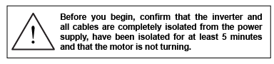
- STO does not isolate the electrical supply. Therefore, the VSD must be isolated from the supply before any maintenance is carried out.
Connection Details:
The ACS180 is supplied with links configured so that the ACS180 can be used with STO disabled.
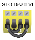
If STO is to be used, remove the links and insert a suitable safety circuit.
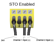
When a dual-channel safety device is wired to the ACS180 and both channels are closed (safe), the VSD can be operated as normal.
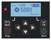
If one or both channels open, the ACS180 will indicate an STO fault and cannot be operated. When the safety circuit changes to closed (safe), the ACS180 can be reset by pressing the OK key.
How to Reset the Inverter to Factory Defaults
Resetting to factory defaults will reset all parameter values, including the motor values.
Press the Back key repeatedly until the home screen is visible.
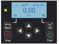
Press the OK key to access the Main Menu, then use the Down arrow key to locate the Parameter menu. Press OK to select it.
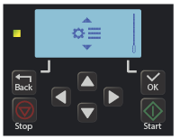
This is the parameter submenu. Use the Down arrow key to select the factory icon as indicated below.
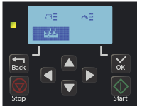
Press OK to select the factory icon.
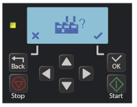
There will now be two options: X (Cancel) or Tick (Proceed).
Pressing "Back" will select X (Cancel), and pressing "OK" will select Tick (Proceed).
To reset the ACS180, press OK to start the reset process.
During the reset process, the screen will go blank and you will be able to hear the internal relay switch off and on.
When complete, the home screen will appear.

ACS180 Easy Start Guide is a pdf version of the above document in a booklet format. If more information is required the ABB ACS180 documents are given below
ABB ACS180 Firmware Manual is an ABB document that gives you information about all the parameters required for commissioning.
ABB ACS180 Hardware Manual is an ABB document that gives you all the installation and rating details required for commissioning.
Important Notice
All images on this page are the property of Inverter Drive Supermarket and must not be copied; they are provided for reference only.
Created by Inverter Drive Supermarket Ltd; last revised September 2026.